How to make a heater with your own hands: instructions for making a homemade device. How to make the simplest and cheapest heater How to make a homemade cheap electric heater
Housing and communal services are in no hurry to start heating season and it’s cold in the apartments, you need to heat the garage or greenhouse, but you never know why there might be a need for a heater. On sale you can find devices for every taste and budget. And yet, many people prefer to assemble the heater with their own hands, saving significant money.
Requirements for a homemade device
Most of those who want to try their hand at making a heater themselves are unlikely to strive for too difficult a job.
And the purchase of a large number of different technical elements and components, the cost of which is quite comparable to the price finished product, is hardly economically justified. Thus, the future device should be:
- easy to install;
- productive;
- economical in energy consumption;
- safe;
- profitable, that is, the costs of its production should be minimal;
- convenient;
- compact.
Considering existing heaters produced by industry, we can conclude that all these requirements are met by devices operating on the principle of infrared radiation. More precisely, the so-called thermal films. The material generates thermal energy that is transferred to objects, which, in turn, heat the environment. This heating method is considered the most effective, since the generated heat is not wasted. Accordingly, the efficiency of such a device is very high.
Homemade product #1 - based on the “Good Warmth” heater
Many heating devices operate according to the so-called “thermal film principle”. For example, the well-known “Kind Warmth”. Assembling its analogue at home will not be difficult. For this you will need:
- Laminated paper plastic. Two sheets of equal size with an area of about 1 square. m.
- Graphite powder. You can grind graphite yourself, for example, old graphite trolleybus brushes.
- Epoxy adhesive.
- A piece of good wire with a plug at the end.
Heater Good Warmth - a prototype for many homemade devices
The work is carried out in stages:
- Mix the glue with graphite powder and stir the resulting mixture thoroughly. Thus, we get not just an adhesive composition, but a graphite conductor with high resistance. The amount of graphite in the glue directly affects the maximum temperature of the future heater. On average it is about 65 °C.
- Apply the prepared composition onto a sheet of plastic using wide, zigzag strokes. For processing we use the rougher side of the sheet.
- We connect the plastic sheets together using epoxy glue.
- For greater structural strength, we construct a wooden frame that securely fixes the sheets.
- We attach copper terminals to the graphite conductors on different sides of the structure. As an option, you can also connect a simple thermostat, which will allow you to set the most comfortable heating mode. However, this is not necessary.
- Dry the structure thoroughly. Even slight humidity will damage the homemade heater the first time you try to turn it on.
- We carry out tests and measure the resistance of the device. Based on the obtained value, we calculate the power and determine whether the heater can be safely connected to the network.
The device is ready for use. It can be placed on the floor or on the wall, does not take up much space, is quite effective and safe, provided it is insulated with high quality.
Graphite is crushed and mixed with epoxy glue to create a graphite conductor.
Homemade #2 - mini heater made of foil and glass
The following homemade device works on a similar principle to the previous one. To make it you will need:
- two pieces of glass of the same size;
- aluminium foil;
- sealant;
- regular paraffin candle;
- wire with a plug at the end;
- epoxy adhesive.
A device for holding the candle while working, cotton swabs for removing soot, and a cloth for cleaning glass will also come in handy.
The inner surface of the glass is coated with soot to create a conductive layer
Let's start assembling:
- We thoroughly clean the glass of all kinds of contaminants: traces of paint, dust, grease, etc.
- We form a conductive surface. To do this, using a candle, we evenly apply soot to one side of each glass blank, which will act as a conductor. To facilitate the process, it is better to cool the glass before the operation - this way the soot will settle more evenly.
- Using a cotton swab, carefully remove excess soot from the edges of the workpiece so that you get a transparent edge about half a centimeter wide.
- We cut out two strips of aluminum foil, the width of which corresponds to the size of the conductive surface. They are designed to perform the function of electrodes.
- We lay the workpiece with the soot-covered side up and apply epoxy glue to it. We place the foil electrodes along the edges so that their edges extend beyond the workpiece.
- We cover the part with a second sheet, directed with the smoked layer inward, carefully press and glue. All connections are well sealed.
We carry out tests and measure the resistance of the conductive layer. Now you can calculate the power of the device, which will be equal to the product of the surface resistance and the square of the current. If the obtained value is within the limits permitted by regulatory documentation, the device can be plugged into a power outlet. If not, you will have to reassemble it. It should be taken into account that the wider the soot layer, the lower the resistance of the device and, accordingly, the higher the heating temperature of the glass.
Model of a homemade glass plate heater
Another simple homemade device works on the principle of using infrared radiation, which can be assembled in a few minutes. This device consists of a sheet of aluminum foil mounted on a radiator and oriented towards the room. The heat emanating from the radiator is collected by the foil mirror and reflected into the room, without unnecessary losses in heating the walls.
There are many ways to make a heater with your own hands. You can choose different principles the operation of the devices and the materials from which they will be made. The main thing is not to forget that the devices are mandatory must be safe. There is no need to be lazy, measure the resistance and calculate the power in order to determine whether it is permissible to plug the homemade product into an outlet or not. All device contacts, wires, and conductive parts must be carefully insulated. A safe, efficient and practical heater will long years delight with your impeccable service.
Central heating comes on late in the fall, while it switches off early in the spring. And Russian winters are so harsh that heating system unable to cope with the needs of the townspeople: the apartments are cold, the heat quickly escapes through the windows. The way out of the situation is to use an additional heat source. Best choice will become infrared heater, which you can build with your own hands.
To make an infrared heater from scrap materials, it is necessary to study the operating principle. How can you do something you know nothing about?
All heated bodies radiate heat, just like the Sun does. The rays emanating from a heat source are electromagnetic waves that heat bodies encountered in their path: pieces of furniture and people. In this case, the air does not heat up: the air receives only part of the heat during heat transfer from already heated bodies. Infrared heaters operate on the principle of thermal radiation, which includes two main elements:
- Radiation source. In heaters industrial production these are thin metal threads that heat up when an electric current passes through them, or lamps (incandescent, halogen, quartz and others);
- . This is a highly reflective body, the function of which is to reflect infrared rays to disperse heat throughout the apartment or form separate heated zones.
Advice! To check the effect achieved by the reflector, take some food foil and hold it near your hand for a while. You will feel the heat, which is reflected and directed towards you.
Another important part in industrial infrared fireplaces is the controller, which regulates the degree of heating of the emitter. IN homemade structures it may not exist. But its installation gives the advantage of being able to set the desired temperature range. The controller automatically causes the device to heat up if the temperature drops below normal, and cool down if the temperature exceeds it.
If you study the infrared ceiling heater, the operating principle will be the same as that of the floor/wall design. The only difference is in the installation method of the IR fireplace. But it depends on him which zones in the room will be more comfortable.
The figure shows the advantage of infrared heaters: heat reaches physical bodies and is absorbed by them, remaining there. Therefore, it may be warmer on the floor than under the ceiling. And when heating a house using the convection method, the floor is always cold: the coating itself does not receive heat. Heat is carried by air, which, when heated, rushes upward, and a new portion of cold air falls down.
Cheap and cheerful
Typically, devices that are heated by electricity are used as an emitter - incandescent filaments or lamps. But the simplest version of the emitter is a heating radiator. This is the same physical body as the Sun. And it can also emit heat. Stand by the radiator and feel the emanating heat - this is radiation. It just spreads in all directions. Why heat the walls if you can direct the rays towards the living space?
Take the foil, smooth it well to improve the reflective effect and stick it on the wall behind the radiators and radiators. As a result, the heat that the walls could receive will be directed in the opposite direction - towards you. This method helps to get up to 20% more heat without any tricks. The only drawback is the ugliness of the reflective screen: it spoils the interior.

Attention! Instead of foil, you can use heat insulators with a reflective screen. A striking example The material used is penofol, one or both sides of which are foil-coated.
A homemade infrared heater can be made from an old reflector Soviet made. In addition to this, you will need:
- Nichrome thread;
- Steel rod;
- Fireproof dielectric (ceramic plate is suitable).

To make an IR fireplace from these things, follow the instructions:
- Remove dirt from the reflector;
- Check the plug, cord and terminals to turn on the coil (they must be intact);
- Measure the length of the spiral that is wound around the reflex cone;
- Cut a steel rod the same length as the spiral;
- Wind a nichrome thread onto the rod so that there are 5 turns for every centimeter;
- Carefully remove the rod from the nichrome winding;
- Place the spiral on a plate (another dielectric) so that the turns do not touch each other;
- Connect the ends of the nichrome spiral to the mains;
- Now the heated spiral will easily fit into the grooves of the cone from the reflector;
- Connect the ends of the spiral to the contacts.
The nichrome filament glows better than the spiral that was in the device before our manipulations. As a result, we get a powerful emitter, the energy of which is reflected from the walls of the reflector and hits opposing bodies, which begin to absorb heat.
Heater glass + aluminum foil
You will need:
- Foil;
- Two glasses of the same size;
- Paraffin candle;
- Sealant;
- A wire with a plug at the end;
- Cotton napkin;
- Boxed;
- Cotton swabs;
- Any device for holding a candle.

Step-by-step instruction:
- Clean the glass with a napkin from paint, dust, grease;
- Light a candle. Place it in a glass, candlestick, or simply drip paraffin onto a flat surface and quickly place the candle on the puddle;
- Smoke the glass on one side by passing it over the fire at the same speed. The soot will lie evenly if the glass is cooled before the procedure. The dark layer will eventually become a conductive element;
- Run cotton swabs around the perimeter of the glass pieces so that you get a frame of clean glass 0.5 centimeters thick;
- Measure the width of the smoked rectangles on the glass with a ruler;
- Cut two rectangles of the same width from foil - these will be electrode strips;
- Take one glass and place it with the smoked side up;
- Apply boxing agent to it and place rectangles of foil on the edges so that they extend beyond the glass;
- Place the second glass on top with the smoked side down and press well so that the structure sticks well;
- Along the perimeter of the “layer cake”, spread sealant at the joints of the glass;
- Check the power of the structure. If it is not higher than 100 W at square meter premises, then the heater can be connected to the network using a wire and plug;
- To connect to the network, use a wooden block with metal plates reinforced at both ends. Solder a plug to one contact. If you install the glass on a block so that the foil coming out from the sides fits tightly to the metal contacts, you get a full-fledged heater.

Attention! To calculate the power of a structure, use a multimeter to measure the resistance of the conductive layer. Since the current strength in the circuit depends on the load, it is better to calculate the power using a more stable parameter - this is the voltage, which in the network is equal to 220 Volts. To do this you will need a formula: N=U*U/R.
N– required power.U– voltage (220V).R– measured resistance. Example: when measuring, we got 24 Ohms. Substitute into the formula:N=220*220/24. We get 2016 watts. This is enough to heat a room with an area of 19-20 square meters.
If your power is more than 100 watts per square meter, then it needs to be reduced by increasing the resistance (we cannot change the network voltage). If the power is very low, then it needs to be increased.
What to do if the power is not suitable?
Now let’s talk about how to make an infrared heater with your own hands of the required power. To do this, you need to know the area of the room you want to heat. For example - 15 meters. Now you need to calculate the maximum permissible power at the rate of 100 watts per meter. Since we have 15 of them, the power will be 15 * 100 = 1500 Watts (it is necessary to count in them, despite the fact that in the passports of electrical appliances it is indicated in kW).
If the voltage is constant (220 Volts), then you can calculate the required resistance. To do this, we derive the resistance from the formula given above: R=U*U/N. Substituting the calculated power and voltage into the formula, we get: R= 220*220/1500=32 Ohms (approximately).
In the example above we had 24 ohms. This means that the resistance needs to be increased. To do this, you need to reduce the width of the smoked strip on the glass. This comes out of the formula R=l*p/S. Where l– length of the conductive layer (constant value, because we will not cut glass), R– resistivity (constant), S– cross-sectional area of the conductive layer, which depends on its width. The wider the layer, the lower the resistance, the narrower it is, the greater it is.
Conclusion! To achieve the required resistance, you need to experimentally select it, making the soot strip narrower or wider, depending on whether you need to increase or decrease the resistance. In this case, each time you will have to disassemble the glass structure.
Heater based on laminated plastic
To assemble a homemade infrared fireplace you will need:
- Laminated paper plastic - 2 pieces with an area of 1 square meter;
- Boxed;
- Graphite (you can buy powder or get it from old batteries, from a pencil - but you will have to crush it);
- Copper plates;
- Wood;
- Plug with cord.

If everything is there, start assembling:
- Mix graphite powder with bauxide to form a thick mass with high resistance;
- Place the plastic sheet with the rough surface facing the table;
- Apply bauxide mixed with graphite onto the plastic using zigzag strokes;
- Prepare the second sheet of plastic in the same way;
- Glue both plastic sheets together, pressing them tightly together;
- On opposite sides of the plates, attach copper plates that will act as terminals;
- Build a wooden frame into which you will need to insert the resulting structure;
- Allow the future heater to dry;
- Measure the conductor resistance and calculate the power.

Attention! Here, the calculation of power and resistance is carried out using the same method as in the previous case. Only the resistance will depend not on the width of the conductive layer, but on the graphite content in the box. The more powder, the higher the resistance, and vice versa.
You will have to disassemble and reassemble the structure several times before you experimentally achieve the required power. Only then can you connect the device to the plug and connect it to the network for operation.
Mini heater made from a shoe polish can
Prepare materials:
- Flat shoe polish box;
- Two conductors;
- Can;
- Graphite powder;
- Sand;
- Plug.
Step-by-step instruction:
- Wash the box;
- Mix sand with graphite powder, taking them in equal quantities;
- Pour the mixture into the box, filling it halfway;
- Cut a circle out of tin;
- Attach a wire to it;
- Place the circle on top of the graphite-sand mixture;
- Add enough sand and graphite until the jar is full;
- Close the jar with a lid to create pressure inside;
- Connect the second wire to the body of the can and connect it to the network using a plug (you can use a car battery).
To regulate the degree of heating, screw the lid of the jar looser or tighter to change the pressure inside. The tighter the jar is twisted, the stronger the heating, and vice versa. But do not allow it to overheat, at which point the jar begins to emit yellow or orange light rays. In this case, the contents inside the can are sintered, causing the efficiency of the heater to decrease significantly. To improve performance after sintering, you need to shake the jar vigorously - then the graphite-sand mixture will again become loose and suitable for work.
A simple homemade panel heater: assembly diagram, photo of production.
With the onset of cold weather the theme residential heating becomes relevant, and many are wondering how to additionally heat, living room, workroom, cottage or garage using a heater. In this article we will look at how to make a simple, cheap and at the same time safe electric heater.
The cross-section and length of the wire must be selected based on the required power of the heater; you can use the table provided.
If you need a 500 W heater, you will need nichrome wire with a cross section of 0.4 mm and a length of 9.7 meters.
To calculate the length of the wire, you can use the table.
You will also need materials:
- Epoxy adhesive.
- Bolts, washers, nuts – 2 pcs.
- Wire and plug.
Electrical diagram of a homemade heater.
Let's start making the heater.
Each sheet of fiberglass needs to be cleaned on one side with a grinding machine, this will inner side heater.
We take one sheet of fiberglass, we will lay nichrome wire on it. Depending on the size of the sheet, you need to calculate the number of turns of wire, taking into account the distance from all edges of the sheet of 20 - 30 mm. The optimal distance between turns is 10 - 15 mm.
For example: if our fiberglass sheet is just over a meter long, then to lay 24 meters of wire you will need to make approximately 24 turns.
For convenience, before laying the wire, it is advisable to draw a frame for the turns on the sheet.
Now you need to lay the wire in coils along the frame; you can fix the coils with paper strips and Monolith glue.
At the point where the wire exits, you need to drill two holes in the fiberglass, make terminals and connect the cord to the plug.
We check the integrity of the circuit with the device.
Now you need to glue the second sheet of fiberglass to the first using epoxy glue. Epoxy glue is applied along the edges of the sheet and between the turns of wire.
We glue the sheets together so that the sheets stick together evenly, they need to be laid on a flat surface, pressed on top with a sheet of chipboard or plywood and pressed down with a weight. After a day, the sheets will firmly stick together and the heater will be ready.
A homemade heater can be hung on the wall, and it will not take up space in the room.
The heater itself is safe, since the heating element is hidden in fiberglass, which is an insulating material, but you still need to follow safety precautions and not leave the heater unattended.
Those who want to make a heater with their own hands are not decreasing: the prices for factory-made autonomous heating devices are not encouraging, and their declared characteristics often turn out to be overpriced compared to the real ones. It is useless to make claims: manufacturers always have an “iron excuse” - the efficiency of heating a room strongly depends on its thermal properties. Cases where it was possible to “squeeze” compensation out of a manufacturer for the consequences of an accident that occurred due to the fault of their product are also rare. True, although it is not prohibited by law to make household heaters yourself, trouble caused by a homemade product will be a serious aggravating circumstance for its manufacturer and owner. Therefore, this article further describes how to correctly design and manufacture safe household heaters of several systems, which are not inferior in thermal efficiency to the best industrial designs.
Constructions
Amateur craftsmen build heaters that are often very intricate in design, see photo in Fig. Sometimes they are done carefully. But overwhelming most of those described in RuNet are homemade heating devices have one thing in common: the high degree of danger they create, harmoniously combined with the complete discrepancy between the expected technical characteristics and the actual ones. First of all, this relates to reliability, durability and transportability.

Make a heater for your home. premises or a camping autonomous one for summer cottages, tourism and fishing, the following systems are possible (from left to right in the figure):
- With direct air heating using natural convection - an electric fireplace.
- With forced blowing of the heater - fan heater.
- With indirect air heating, natural convection or forced air flow - oil or water-air heater.
- In the form of a surface emitting thermal (infrared, IR) rays - a thermal panel.
- Fiery autonomous.
The latter differs from a stove, stove or hot water boiler in that most often it does not have a built-in burner/furnace, but uses waste heat from heating and cooking appliances. However, the line here is very blurred: gas heaters with a built-in burner are commercially available and can be made independently. Many of them can be used to cook or reheat food. Here, at the end, a flame heater will also be described, which is not wood-based, not liquid fuel, not gas-based, and certainly not a stove. And the others are considered in descending order of their degree of safety and reliability. Which, nevertheless, with proper execution and in the “worst” samples, fully comply with the requirements for household autonomous heating devices.
Thermal panel
This is quite complex and labor-intensive, but the safest and most effective type of household electric heater: a double-sided thermal panel for 400 W in a 12 sq. m room. m in a concrete house heats from +15 to +18 degrees. The required power of the electric fireplace in this case is 1200-1300 W. The cost of making a thermal panel yourself is small. Thermal panels work in the so-called. far (more distant from the red region of the visible spectrum) or long-wave IR, so the heat is soft, not burning. Due to the relatively weak heating of the heat-emitting elements, if they are made correctly (see below), the operational wear of thermal panels is practically absent, and their durability and reliability are limited by unforeseen external influences.
The heat-emitting element (emitter) of a thermal panel consists of a thin flat conductor made of a material with high electrical resistivity, sandwiched between 2 plates - dielectric plates transparent to IR. Thermal panel heaters are made using thin-film technology, and the covers are made from a special plastic composite. Both are unavailable at home, so many hobbyists are trying to make heat emitters based on a carbon coating sandwiched between 2 glasses (item 1 in the figure below); ordinary silicate glass is almost transparent to IR.
This technical solution is a typical surrogate, unreliable and short-lived. The conductive film is obtained either from candle soot or by spreading an epoxy compound filled with ground graphite or electrical carbon onto the glass. The main drawback of both methods is the uneven film thickness. Carbon in the amorphous (coal) or graphitic allotropic modification is a semiconductor with high intrinsic conductivity for this class of substances. The effects characteristic of semiconductors appear in it weakly, almost imperceptibly. But with increasing temperature of the conductive layer, the electrical resistivity of the carbon film does not increase linearly, like that of metals. The consequence is that thin areas heat up more and burn out. The current density in the thicker ones increases, they heat up, they also burn out, and soon the entire film burns out. This is the so-called. avalanche burnout.
In addition, the soot film is very unstable and quickly crumbles on its own. To obtain the required heater power, up to 2 volumes of carbon filler must be added to the epoxy glue. In fact, up to 3 is possible, and if you add 5-10% by volume of a plasticizer - dibutyl phthalate - to the resin before adding the hardener, then up to 5 volumes of filler. But the ready-to-use (not hardened) compound turns out to be thick and viscous, like plasticine or fatty clay, and it is unrealistic to apply it with a thin film - epoxy sticks to everything in the world except paraffin hydrocarbons and fluoroplastic. You can make a spatula out of the latter, but the compound behind it will stretch out in clumps and lumps.
Finally, graphite and coal dust are very harmful to health (have you heard about silicosis in miners?) and extremely dirty substances. It is impossible to remove or wash away their traces; soiled things have to be thrown away, they stain others. Anyone who has ever dealt with graphite lubricant (this is the same finely crushed graphite) - as they say, I will live, I will not forget. That is, homemade emitters for thermal panels need to be made in some other way. Fortunately, calculations show that the “good old”, proven over many decades and inexpensive nichrome wire is suitable for this.
Calculation
Through 3-mm window glass, approx. 8.5 W/sq. dm IR. From the “pie” of the thermal panel emitter, 17 W will go in both directions. Let's set the dimensions of the emitter to 10x7 cm (0.7 sq. dm); such pieces can be cut from culls and cutting waste in almost unlimited quantities. Then one emitter will give us a room of 11.9 W.
Let's take the heater power to be 500 W (see above). Then you will need 500/11.9 = 42.01 or 42 emitters. Structurally, the panel will consist of a matrix of 6x7 emitters with dimensions without frames of 600x490 mm. Let's put it on a frame up to 750x550 mm - ergonomically it works, it's quite compact.
The current consumed from the network is 500 W/220 V = 2.27 A. The electrical resistance of the entire heater is 220 V/2.27 A = 96.97 or 97 Ohms (Ohm’s law). The resistance of one emitter is 97 Ohm/42 = 2.31 Ohm. The resistivity of nichrome is almost exactly 1.0 (Ohm * sq. mm)/m, but what cross-section and length of wire is needed for one emitter? Will the nichrome “snake” (item 2 in the figure) fit between 10x7 cm glass?

Current density in open, i.e. in contact with air, nichrome electric spirals - 12-18 A/sq. mm. They glow from dark to light red (600-800 degrees Celsius). Let's take 700 degrees at a current density of 16 A/sq. mm. Under the condition of free IR radiation, the temperature of nichrome depends on the current density approximately by the square root. Let's reduce it by half, to 8 A/sq. mm, we get operating temperature nichrome at 700/(2^2) = 175 degrees, for silicate glass safely. The temperature of the outer surface of the emitter (without taking into account heat removal due to convection) will not exceed 70 degrees with an outer surface of 20 degrees - it is suitable both for heat transfer by “soft” IR and for safety if you cover the emitting surfaces with a protective mesh (see below).
A rated operating current of 2.27 A will give a nichrome cross section of 2.27/8 = 0.28375 sq. mm. Using the school formula for the area of a circle, we find the diameter of the wire - 0.601 or 0.6 mm. Let us take it with a margin of 0.7 mm, then the heater power will be 460 W, because it depends on its operating current squared. 460 W is enough for heating; 400 W would be enough, and the durability of the device will increase several times.
1 m of nichrome wire with a diameter of 0.7 mm has a resistance of 2.041 Ohms (0.7 squared = 0.49; 1/0.49 = 2.0408...). To obtain a resistance of one emitter of 2.31 Ohms, you will need 2.31/2.041 = 1.132... or 1.13 m of wire. Let's take the width of the nichrome “snake” to be 5 cm (1 cm of margin at the edges). Add 2.5 mm per turn of 1 mm nails (see below), for a total of 5.25 cm per snake branch. The branches will be needed 113 cm/5.25 cm = 21.52..., let's take 21.5 branches. Their total width is 22x0.07 cm (wire diameter) = 1.54 cm. Let's take the length of the snake to be 8 cm (1 cm of margin from the short edges), then the wire laying coefficient is 1.54/8 = 0.1925. In the lousiest Chinese low-power power transformers it is approx. 0.25, i.e. We have plenty of space for the bends and gaps between the branches of the snake. Phew, the fundamental issues have been resolved, we can move on to R&D (experimental design work) and technical design.
OCD
The thermal conductivity and transparency of IR silicate glass vary greatly from brand to brand and from batch to batch. Therefore, first you will need to make 1 (one) emitter, see below, and test it. Depending on their results, you may have to change the diameter of the wire, so do not buy a lot of nichrome at once. In this case, the rated current and power of the heater will change:
- Wire 0.5 mm – 1.6 A, 350 W.
- Wire 0.6 mm - 1.9 A, 420 W.
- Wire 0.7 mm - 2.27 A, 500 W.
- Wire 0.8 mm - 2.4 A, 530 W.
- Wire 0.9 mm - 2.6 A, 570 W.
Note: who is literate in electricity - the rated current, as you can see, does not change according to the square of the wire diameter. Why? On the one hand, thin wires have a relatively large radiating surface. On the other hand, with a thick wire, the permissible IR power transmitted by the glass cannot be exceeded.
For testing, the finished sample is installed vertically, supported by something non-flammable and heat-resistant, on a fireproof surface. Then the rated current is supplied to it from an regulated power source (PS) of 3 A or more or LATP. In the latter case, the sample cannot be left unattended during the entire test! The current is controlled by a digital tester, the probes of which must be tightly compressed with the current-carrying wires using a screw with a nut and washers. If the prototype is powered by a LATR, the tester must measure the force alternating current(limit AC 3A or AC 5A).
First of all, you need to check how the glass behaves. If it overheats and cracks within 20-30 minutes, then the entire batch may be unusable. For example, dust and dirt become embedded in used glass over time. Cutting them is sheer torment and death. diamond glass cutter. And such glass cracks at much lower heat than new glass of the same type.
Then, after 1-1.5 hours, the strength of the IR radiation is checked. The temperature of the glass is not an indicator here, because... The main part of the IR is emitted by nichrome. Since you most likely will not have a photometer with an IR filter, you will have to check it with your palms: they are held parallel to the emitting surfaces at a distance of approx. 15 cm from them for at least 3 minutes. Then, for 5-10 minutes, you should feel even, soft warmth. If the IR from the emitter begins to burn the skin immediately, reduce the diameter of the nichrome. If after 15-20 minutes you don’t feel a slight burning sensation (like during solar heating in the middle of summer), you need to take thicker nichrome.
How to bend a snake
The design of the emitter of a homemade panel heater is shown in pos. 2 fig. higher; The nichrome snake is shown conditionally. Glass plates cut to size are cleaned of dirt and washed with a brush in water with the addition of any dishwashing detergent, then also washed with a brush under running water. clean water. “Ears” - contact lamellas measuring 25x50 mm made of copper foil - are glued to one of the covers with epoxy glue or instant cyanoacrylate (superglue). The overlap of the “ear” on the lining is 5 mm; 20 mm sticks out. To prevent the lamella from falling off before the glue has set, place something 3 mm thick (the thickness of the lining glass) under it.
Next you need to form the snake itself from nichrome wire. This is done on a mandrel template, the diagram of which is given in pos. 3, and a detailed drawing is in Fig. Here. The “tails” for annealing the snake (see below) should be given at least 5 cm. The bitten ends of the nails are sanded to roundness on an emery stone, otherwise it will be impossible to remove the finished snake without crushing it.

Nichrome is quite elastic, so the wire wound on the template must be annealed so that the snake holds its shape. This should be done in semi-darkness or low light. The snake is supplied with a voltage of 5-6 V from a power supply of at least 3 A (this is why a fireproof lining is needed on a tree). When the nichrome glows cherry, turn off the current, allow the thread to cool completely, and repeat this procedure 3-4 times.
The next step is to press the snake with your fingers through the plywood strip placed on it and carefully unwind the tails wound on 2-mm nails. Each tail is straightened and shaped: a quarter of a turn remains on a 2-mm nail, and the rest is cut flush with the edge of the template. The remainder of the “tail” of 5 mm is cleaned with a sharp knife.
Now the snake needs to be removed from the mandrel without damaging it, and secured to the substrate, ensuring reliable electrical contact of the leads with the lamellas. Remove with a pair of knives: their blades are slipped from the outside under the bends of the branches on 1-mm nails, carefully pry up and lift the crimped thread of the heater. Then the snake is placed on the substrate and the leads are bent a little, if necessary, so that they lie approx. in the middle of the slats.
Nichrome cannot be soldered with metal solders with inactive flux, and the remaining active flux can corrode the contact over time. Therefore, nichrome is “soldered” to copper, so-called. liquid solder - conductive paste; It is sold in radio stores. A drop of liquid solder is squeezed onto the contact of the stripped nichrome with copper and through a piece polyethylene film press down with your finger so that the paste does not stick out upward from the wire. You can immediately press it down with some flat weight instead of your finger. Remove the weight and film after the paste has hardened, from an hour to a day (the time is indicated on the tube).
The “solder” has frozen – it’s time to assemble the emitter. Along the middle we squeeze a thin, no thicker than 1.5 mm, “sausage” of ordinary construction silicone sealant onto the snake, this will prevent the wire bends from slipping and closing. After this, we squeeze out the same sealant with a thicker roller, 3-4 mm, along the contour of the substrate, retreating from the edge of approx. by 5 mm. We apply a cover glass and very carefully so that it does not slide to the side and pull the snake along with it, press down until it fits tightly, and set the emitter aside to dry.
The drying rate of silicone is 2 mm per day, but after 3-4 days, as it may seem, it is still impossible to take the emitter into work further; you need to let the inner roller that fixes the bends dry. You will need approx. a week. If many emitters are made for a working heater, they can be dried in a stack. The bottom layer is laid out on plastic film, and covered with it on top. Elements following. layers are laid across the underlying ones, etc., separating the layers with film. The stack, for guarantee, takes 2 weeks to dry. After drying, the protruding excess silicone is cut off with a safety razor blade or a sharp mounting knife. Silicone deposits must also be completely removed from the contact lamellas, see below!
Installation
While the emitters are drying, we make 2 identical frames from slats of hard wood (oak, beech, hornbeam) (item 4 in the figure with the diagram of the panel heater). The connections are made by cutting into half the wood and fastened with small self-tapping screws. MFD, plywood and wood materials with synthetic binders (chipboard, OSB) are not suitable, because prolonged heating, even if not strong, is strictly contraindicated for them. If you have the opportunity to cut frame parts from textolite or fiberglass, that’s generally great, but ebonite, bakelite, textolite, carbolite and thermoplastic plastics are not suitable. Before assembly, wooden parts are impregnated twice with a water-polymer emulsion or half-diluted acrylic varnish water based.
Ready-made emitters are placed in one of the frames (item 5). The overlapping lamellas are electrically connected by drops of liquid solder, as are the jumpers on the sidewalls, forming a series connection of all emitters. It is better to solder the supply wires (from 0.75 sq. mm) with ordinary low-melting solder (for example, POS-61) with inactive flux paste (composition: rosin, ethyl alcohol, lanolin, see on the bottle or tube). Soldering iron - 60-80 W, but you need to solder quickly so that the emitter does not come unglued.
The next step at this stage is to apply a second frame and mark on it where the supply wires are located; grooves will need to be cut for them. After this, we assemble the frame with the emitters using small screws, pos. 6. Take a closer look at the location of the fastening points: they should not fall on live parts, otherwise the fastening heads will be energized! Also, in order to prevent accidental contact with the edges of the lamellas, all ends of the panel are covered with non-flammable plastic with a thickness of 1 mm, for example. PVC with chalk filling from cable channels(boxes for wiring). For the same purpose, and for greater structural strength, silicone sealant is applied to all joints of the glass and frame parts.
The final steps are firstly the installation of legs with a height of 100 mm. Sketch wooden legs panel heater is given at pos. 7. The second is to apply a protective steel mesh made of thin wire with a mesh size of 3-5 mm to the sidewalls of the panel. Third, the cable entry is designed with a plastic box: it houses contact terminals and a light indicator. Possibly a thyristor voltage regulator and a protective thermal relay. That's it, you can turn it on and warm up.
Thermal painting
If the power of the described thermal panel does not exceed 350 W, a picture heater can be made from it. To do this, foil insulation is applied to the back side, the same one that is used for thermal insulation. Its foil side should be facing the panel, and the porous plastic side should be facing out. The front side of the heater is decorated with a fragment of photo wallpaper on plastic; thin plastic is not such an obstacle for IR. In order for the picture-heater to warm better, you need to hang it on the wall at an angle of approx. 20 degrees.
What about foil?
As you can see, a homemade panel heater is quite labor-intensive. Is it possible to simplify the work by using, say, aluminum foil instead of nichrome? The thickness of the baking sleeve foil is approx. 0.1 mm, seems to be a thin film. No, the point here is not the thickness of the film, but the resistivity its material. For aluminum it is low, 0.028 (Ohm * sq. mm)/m. Without giving detailed (and very boring) calculations, we will indicate their result: the area of a thermal panel with a power of 500 W on an aluminum film 0.1 mm thick turns out to be almost 4 square meters. m. Still, the film turned out to be a bit thick.
12 V
A homemade fan heater can be quite safe in a low-voltage, 12 V version. You can’t get more than 150-200 W of power from it; it will need a step-down transformer or IP that is too large, heavy and expensive. However, 100-120 W is just enough to keep a small plus in the basement or cellar all winter, which protects against frozen vegetables and cans of homemade products bursting from frost, and 12 V is the voltage permissible in rooms with any degree of danger of electric shock. You cannot put more in the basement/cellar, because... According to electrical engineering classification, they are especially dangerous.
The basis of the 12 V fan heater is an ordinary red working hollow (hollow) brick. A one and a half thickness of 88 mm (top left in the figure) is best suited, but a double thickness of 125 mm (bottom) will also work. The main thing is that the voids are through and identical.

The design of a 12 V “brick” fan heater for the basement is shown there in Fig. Let's do the math nichrome heating coils for him. We take a power of 120 W, this is with some reserve. Current, respectively, 10 A, heater resistance 1.2 Ohm. On the one hand, the spirals are blown. On the other hand, this heater must work for a long time without supervision in a fairly harsh conditions. Therefore, it is better to connect all the spirals in parallel: one will burn out, the rest will be pulled out. And it’s convenient to regulate the power - just turn off 1-2 or several coils.
There are 24 channels in a hollow brick. The spiral current of each channel is 10/24 = 0.42 A. Not enough, nichrome is needed very thin and, therefore, unreliable. This option would be suitable for a household fan heater up to 1 kW or more. Then the heater must be calculated, as described above, for a current density of 12-15 A/sq. mm, and divide the resulting wire length by 24. To each segment, 20 cm are added into 10-cm connecting “tails”, and the middle is twisted into a spiral with a diameter of 15-25 mm. With "tails" all the spirals are connected in series using clamps made of copper foil: its tape 30-35 mm wide is wound in 2-3 layers onto folded nichrome wires and twisted into 3-5 turns with a pair of small pliers. To power the fans, you will have to install a low-power 12 V transformer. This heater is well suited for a garage or warming up a car before a trip: like all fan heaters, it quickly warms up the middle of the room, without wasting heat on heat loss through the walls.
Note: Computer fans are often called coolers (literally – coolers). In fact, a cooler is a cooling device. For example, a processor cooler is a finned radiator in a block with a fan. And the fan itself is also a fan in America.
But let's go back to the basement. Let's see how much nichrome is needed for a reduced to 10 A/sq. mm for reliability reasons current density. The wire cross-section is clear without calculations - 1 sq. mm. Diameter, see calculations above – 1.3 mm. Such nichrome is on sale without difficulty. The required length for a resistance of 1.2 Ohm is 1.2 m. What is the total length of the channels in the brick? We take one and a half thickness (weighs less), 0.088 m. 0.088x24 = 2.188. So we just need to thread a piece of nichrome through the voids of the brick. It’s possible through one, because According to the calculation, 1.2/0.088 = 13.(67) channels are needed, i.e. 14 is enough. So they heated the basement. And quite reliably - such thick nichrome and strong acid will not quickly corrode.
Note: the brick in the body is fixed with small steel corners on bolts. An automatic protective device must be included in the powerful 12 V circuit, e.g. automatic plug for 25 A. Inexpensive and quite reliable.
IP and UPS
It is better to take (make) an iron transformer for heating a basement with powerful winding taps of 6, 9, 12, 15 and 18 V, this will allow you to regulate the heating power within a wide range. 1.2 mm nichrome with blowing will pull 25-30 A. To power the fans, then you need a separate 12 V 0.5 A winding and also a separate cable with thin wires. To power the heater, cores of 3.5 sq.m. are required. mm. A powerful cable can be the crappiest - PUNP, KG, for 12 V there is no fear of leaks and breakdown.
Maybe you don’t have the opportunity to use a step-down transformer, but you have a switching power supply (UPS) from an unusable computer lying around. Its 5 V channel is enough power; standard - 5 V 20 A. Then, firstly, you need to recalculate the heater to 5 V and the power of 85-90 W so as not to overload the UPS (the wire diameter is 1.8 mm; the length is the same). Secondly, to supply 5 V, you need to connect together all the red wires (+5 V) and the same number of black wires (common GND wire). 12 V for fans is taken from any yellow wire (+12 V) and any black. Thirdly, you need to short-circuit the PC-ON logical start circuit to the common wire, otherwise the UPS simply will not turn on. Usually the PC-ON wire is green, but you need to check: remove the casing from the UPS and look at the markings on the board, on top or on the mounting side.
heating elements
For heaters: types you will have to buy heating elements: 220 V electrical appliances with open heaters are extremely dangerous. Here, pardon the expression, you need to think first of all about own skin with property, whether there is a formal ban or not. It’s easier with 12-volt devices: according to statistics, the degree of danger decreases in proportion to the square of the supply voltage ratio.
If you already have an electric fireplace, but it doesn’t heat well, it makes sense to replace a simple air heating element with a smooth surface (pos. 1 in the figure) with a finned one, pos. 2. The nature of convection will then change significantly (see below) and heating will improve when the power of the finned heating element is 80-85% of the smooth one.

Cartridge heating element in a housing made of of stainless steel(item 3) can heat both water and oil in a tank made of any structural material. If you buy one, be sure to check that the kit includes gaskets made of oil-heat-gasoline-resistant rubber or silicone.
A copper water heating element for a boiler is equipped with a tube for a temperature sensor and a magnesium protector, pos. 4, which is good. But they can only heat water and only in a stainless steel or enameled tank. The heat capacity of oil is much less than that of water, and the body of a copper heating element in oil will soon burn out. The consequences are severe and fatal. If the tank is made of aluminum or ordinary structural steel, then electrocorrosion due to the presence of a contact potential difference between the metals will very quickly eat away the protector, and then eat through the body of the heating element.
T. called. dry heating elements (item 5), like cartridge ones, are capable of heating both oil and water without additional protective measures. In addition, their heating element can be changed without opening the tank and without draining the liquid from there. There is only one drawback - they are very expensive.
Fireplace

You can improve an ordinary electric fireplace, or make your own efficient one based on a purchased heating element, using an additional casing that creates a secondary convection circuit. From a conventional electric fireplace, firstly, the air flows upward in a rather hot but weak stream. It quickly reaches the ceiling and through it warms more of the neighbors' floors, attic or roof than the owner's room. Secondly, the IR coming down from the heating element in the same way warms the neighbors below, the subfloor or basement.
In the design shown in Fig. on the right, downward IR is reflected into the outer casing and heats the air in it. The thrust is further enhanced by the suction of hot air from the inner casing, which is less heated from the outer casing at the narrowing of the latter. As a result, the air from an electric fireplace with a double convection circuit comes out in a wide, moderately heated stream, spreads to the sides without reaching the ceiling, and effectively heats the room.
Oil and water
The effect described above is also produced by oil and water-air heaters, which is why they are popular. Industrially produced oil heaters are made hermetically sealed with a permanent filling, but it is in no case recommended to repeat them yourself. Without an accurate calculation of the volume of the housing, internal convection in it and the degree of oil filling, a rupture of the housing, an electrical failure, oil spillage and fire are possible. Underfilling is just as dangerous as overfilling: in the latter case, the oil simply tears the housing under pressure when heated, and in the former, it first boils. If you make the housing of a deliberately larger volume, then the heater will heat disproportionately weakly compared to the electricity consumption.
In amateur conditions, it is possible to build an oil or water-air heater open type with expansion tank. The diagram of its device is shown in Fig. Once upon a time they made quite a lot of these, for garages. The air from the radiator is slightly heated, the temperature difference between inside and outside is kept minimal, which is why heat loss is reduced. But with the advent of panel heaters, oil-based homemade products are disappearing: thermal panels are better in all respects and are quite safe.

If you still decide to make your own oil heater, keep in mind that it must be reliably grounded, and you only need to fill it with very expensive transformer oil. Any liquid oil gradually bituminizes. Increasing temperature accelerates this process. Motor oils are designed to allow oil to circulate among moving parts due to vibration. Bituminous particles in it form a suspension that only pollutes the oil, which is why it has to be changed from time to time. In the heater, nothing will prevent them from depositing carbon deposits on the heating element and in the tubes, causing the heating element to overheat. If it bursts, the consequences of oil heater accidents are almost always very severe. Transformer oil is expensive because the bituminous particles in it do not settle into soot. There are few sources of raw materials for mineral transformer oil in the world, and the cost of synthetic oil is high.
Fiery
Powerful gas heaters for large premises with catalytic afterburning are expensive, but record-breakingly economical and efficient. It is impossible to reproduce them under amateur conditions: you need a micro-perforated ceramic plate with platinum coating in the pores and a special burner made of parts made with precision precision. At retail, one or the other will cost more than a new heater with a warranty.

Tourists, hunters and fishermen have long come up with low-power afterburner heaters in the form of an attachment to a camp stove. These are also produced on an industrial scale, pos. 1 in Fig. Their efficiency is not so great, but it’s enough to heat the tent until lights out in sleeping bags. The design of the afterburner is quite complex (item 2), which is why factory tent heaters are not cheap. Fans also make a lot of these, from cans or, for example. from automobile oil filters. In this case, the heater can operate both from a gas flame and from a candle, see video:
Video: Portable oil filter heaters
With the advent of heat-resistant and heat-resistant steels in widespread use, lovers of being outdoors are increasingly giving preference to gas camping heaters with afterburning on a grid, pos. 3 and 4 - they are more economical and heat better. And again, amateur creativity combined both options into a combined type mini-heater, pos. 5., capable of working from gas burner, and from a candle.

A drawing of a homemade mini-heater with afterburning is shown in Fig. on right. If it is used occasionally or temporarily, it can be made entirely from tin cans. For an enlarged version for the garden, cans of tomato paste, etc. will be used. Replacing the perforated mesh cover significantly reduces warm-up time and fuel consumption. A larger and very durable version can be assembled from car wheels, see next. video clip. This is already considered a stove, because... You can cook on it.
Video: heater-stove made from a wheel rim
From a candle
A candle, by the way, is a fairly strong source of heat. For a long time this property of hers was considered a hindrance: in the old days, at balls, ladies and gentlemen would sweat, makeup would run, and powder would clump together. How after that they also played cupids, without hot running water and a shower, to modern man difficult to understand.

The heat from a candle in a cold room is wasted for the same reason that a single-circuit convection heater does not heat well: hot exhaust gases rise up too quickly and cool, producing soot. Meanwhile, making them burn out and give heat is easier than a gas flame, see fig. In this system, the 3-circuit afterburner is assembled from ceramic flower pots; baked clay is a good IR emitter. A candle heater is intended for local heating, say, so as not to tremble while sitting at the computer, but just one candle provides a surprising amount of heat. When using it, you only need to open the window slightly, and when going to bed, be sure to extinguish the candle: it also consumes a lot of oxygen for combustion.
During the cold season, the need for heat especially increases. But not every owner has the opportunity to purchase a factory-made heater. There is nothing difficult about assembling a heater with your own hands.
We bring to your attention four options for creating a heating device from improvised means that will perfectly cope with the task assigned to it. We have described in detail the process of making homemade products. Described the principle of operation and features of operation.
TO step by step guides We have attached diagrams, photo selections and video instructions.
The simplest models of homemade heaters are designed for local heating. Their maximum heating temperature is about 40°C.
Most heating homemade products are radiating devices that operate on the same principle as electric radiators. They are connected to a single-phase network with 220 V, traditional for household objects. For those wishing to self-production devices requires knowledge in the field of electrical engineering and electrical installation.
Image gallery


Option 1. Homemade compact thermal film
The heater will be based on two pieces of glass. These are identical rectangles measuring 4x6 cm.
The length and width of the heater's working area may vary. The main thing is that the area of each glass is about 25 square centimeters.
To create such a homemade heater you will also need:
- copper two-core cable;
- multimeter;
- paraffin candle;
- wooden block;
- pliers;
- sealant; epoxy adhesive;
- cotton napkin;
- hygiene sticks.
Before starting work, the cable must be equipped with a plug.

The heating element will be a piece of aluminum foil used by housewives for baking, the thickness of which is 0.1 mm
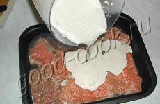
First of all, clean the glass blanks, removing dust and remaining dirt with a napkin, degrease and dry thoroughly. The cleaned workpieces are cooled. This is necessary so that during subsequent firing the carbon deposits better on the surface.
Light a candle placed in a candlestick. And then, one by one, grab each glass piece by the corner with pliers and carefully move it over the candle so that the glass becomes covered with soot. It is necessary to achieve uniform deposition of carbon deposits on the entire surface of the glass; the burned part will act as a conductive element.
Manipulations with the candle will have to be interrupted periodically in order to allow the heated glass to cool slightly.

The main advantage of such a device is that a significant part of the thermal energy is released by the material heated to a certain temperature in the form of infrared radiation
After the workpieces have cooled, the edges of each of them are cleaned. To do this, using hygiene sticks along the perimeter contour, remove 5 millimeters from the edge.
Glue is evenly applied to the burned part, which will act as a conductive element, and a pre-prepared piece of foil is placed on top of it. The strips will serve as the terminals needed to connect the wires.
The same actions are performed with the other half. Both parts are connected. To ensure the tightness of the device, the joints are treated with sealant, covering the end around the entire perimeter.

To make heating elements, two strips are cut out of foil, the width of which corresponds to the size of the smoked area on the glass blanks
In order to calculate the power of the device, it is necessary to measure the resistance of the carbon coating using a tester. The multimeter probes are applied to the hanging “tails” of aluminum foil. The obtained data is used in calculations using the formula:
N=I 2 x R,
Where " N" – power, " I" is the current strength, and " R" - resistance.
The power should not exceed the permissible values of 1.2 W. If the resistance exceeds 120 ohms, in order to reduce it, it is necessary to make the carbon layer a little thicker. The following rule applies here: the more soot, the lower the electrical resistance.
If the parameters are within normal limits, proceed to the final stage of assembly. To do this, the cleaned edges of the workpieces are smeared with glue, and the free ends of the foil sections are folded and glued to one of the sides.

From wooden block make a stand and mount contact pads connected to the electrical cord on it
A structure assembled from glass and foil is installed on a wooden platform and the device is connected to a 12-volt source.
Option #2. Heating panel from the remains of the infrared floor
If, after installing an infrared heating floor, there are scraps of film left over, they should be safely put into production wall heater, for example, for a cottage or garage.

Using scraps of infrared film left over after installing heated floors in the house, you can build a wall panel, and, if desired, decorate it with a laminated large-sized photograph
Infrared film consumes less energy than other heating electrical devices. For a small room of about 2x2 m, 1 m is enough.
Image gallery


Now you need to carefully insulate everything so that the film does not spark at the contacts and does not create any threats during its own operation.
Image gallery


Option #3. Fan heater made from improvised means
We offer one more affordable way manufacturing a homemade device for local heating, which is based on the operating principle. It will take no more than two hours to make. The main advantage of such a device is the ease of manufacture and availability of the necessary materials.
The disadvantages of the design include the fact that during the heating process it will burn oxygen, and in some cases even smell like burning.

The device body will be made of tin can 20 cm high with a diameter of 10 cm, and the strips for winding the nichrome spiral are made of non-foil PCB
In addition to the tin can, to assemble the heating structure you need to prepare:
- 12 Volt transformer;
- diode bridge;
- nichrome wire with a cross section of 1 mm 2;
- fan;
- hammer drill with a thin drill;
- soldering iron;
- computer fan.
It is necessary to pre-cut two blanks from the PCB, the size of which corresponds to the dimensions of the selected can. To connect the device to the network and switch modes, you will also need an electrical cord and a push-button switch.
First of all, remove the foil from a piece of PCB and cut out the inside so that it looks like a frame.

In a textolite blank using thin drill make holes, placing them with a slight offset relative to each other
The ends of the nichrome wire are buried in the holes made. The “tails” of electrical wires, stripped of insulation, are soldered to the free ends of the wire placed under the frame.
The current density in nichrome electrical spirals in contact with air is about 12-18 A/mm 2 . Depending on the degree of heating, their color saturation will change from dark burgundy to bright red. The temperature of the outer surface of the emitter does not exceed 70 degrees.

Take a transformer, a diode bridge and a cooler and close them with a fixed nichrome wire into a single circuit, not forgetting to connect the switch
A diode rectifier and a small-sized 12 V transformer are needed to power the cooler.
To be able to regulate the temperature, it is worth considering the option of installing at least two separated spirals. In addition, by connecting the spirals in parallel, if one burns out, the others will not be affected.
The main thing when assembling the structure is that the wound spirals do not touch any parts other than the textolite frame.
The fan is mounted in the can using a bracket in the form of a U-shaped metal part, secured with a bolt. The current will heat the turns of the wire, and the fan will blow the structure with a warm stream of air.

TO assembled structure PCB is attached, after which the elements of the electrical device connected into a single circuit are placed in a jar
To ensure free access of air, 20-30 holes with a diameter of 1.5-2 mm are drilled in the lid and walls of the jar. The assembled device is directly connected to a 220V network and its functionality is checked. For safety reasons, the radiating surface can be covered with a protective mesh.
This fan heater is suitable for heating a small room. Like industrial ones, it will warm up the middle of the room in just a few minutes, without wasting precious heat on heat loss that passes through the walls.
Image gallery


Those who want to make their own garage heater using improvised materials will find a lot of useful information on another one of our sites.
Homemade low-power devices
The models described above are suitable only for local heating. To heat a room, you need to build a more powerful heater, the manufacturing technology of which will be discussed below.
Option 1. Creation of an oil device
Made with my own hands has high efficiency and is also quite functional and safe. The principle of operation of the device is based on the fact that a heating element located inside the housing heats up the oil located near it, as a result of which the convection movement of flows is activated.

The body of the product can be made from a sectional heating system battery, a car radiator, or welded from steel pipes
To ensure smooth power adjustment, the device is equipped with a rheostat or discrete switches. To automate the process, a thermostat and a rollover sensor are additionally installed.
To make an oil heater you need to prepare in advance:
- Heating element with a power of 1 kW (for a room with an area of 10 square meters);
- durable and sealed housing, the design of which completely eliminates liquid leakage;
- clean and heat-resistant technical oil is taken at the rate of 85% of the total volume of the housing;
- control and automation devices are selected in accordance with the total power load of the device.
An important point when purchasing a cartridge tent, do not forget to check that it comes with silicone gaskets or their analogues, made of oil-heat-gasoline resistant rubber.
In order not to deal with welding, a dismantled one can be used as a housing, dismantled due to the modernization of the public building system.
The design, which is impressive in size, will require the construction of a platform. It can be made from channels or steel angles. When drawing up a diagram, the frames are based on the capacity of the container and the height of the product.

The connection diagram of the device and the assembly sequence of its structural elements are clearly presented in the figure.
Difficulty may arise at the stage of welding elements. After all, to perform the work you need to have the appropriate skills. The first step is to cut the profile pipe into pieces of a given length. Rectangular frames are assembled from them.
A hole is cut out in the corner of the structure to accommodate the heating element. At the highest point of the radiator, a hole is cut out to allow oil to be filled and equipped with a fitting with an external thread, on top of which a cap is installed.

Before putting the heating device into operation, it must be tested for leaks by creating high pressure in the middle of the device
When assembling the structure, you should pay attention to a number of points:
- It is better to place the heating element in the side or bottom of the structure, fixing it with bolted connections. This solution will ensure better oil circulation. Under no circumstances should it come into contact with the body.
- To activate the process of natural convection of liquid, add a pump and electric drive to the design. To fix the pump to the container, you need to weld small metal plates.
- Do not forget to provide openings equipped with valves to allow emergency pressure relief by draining the oil. The pumps are located at the bottom of the radiator in the corners.
- To ensure the durability of the structure, preventing the development of electrocorrosion, take into account the compatibility of the body metal and the heating element. Due to the potential difference between metals, you should not combine ordinary steel or aluminum with copper.
- Be sure to ground the heater.
The structure is not completely filled with oil, but only 85%. This is necessary so that the 15% allocated to air serves as a buffer zone when the oil expands due to increased temperature.
Image gallery

Excellent housing for homemade oil heater an old cast iron battery will become
If there is no point in saving, a completely new bimetallic radiator is suitable for use as a housing for heating equipment


After checking the tightness of the holes, all that remains is to connect the heating element, install the housing and pour oil inside. To increase the mobility of the structure, it can be equipped with wheels and additional elements fastenings
Option #2. Making an infrared device
The undeniable advantage of such a device is that the generated thermal energy released in the form of infrared radiation. Thanks to this, a heater created on the basis of a carbon element warms up not only the air, but also people and objects located in the infrared radiation zone.
The basis of such a device, created according to the type, will be two plastic blanks, the area of each of which is about 1 square. Fine-grained graphite powder will be applied to them, the structure somewhat reminiscent of flour.

Keep in mind that graphite powder, which acts as a conductive mixture, is an extremely dirty substance, and besides, it is very dangerous to health
To make an effectively working IR heater with your own hands, you also need to prepare:
- two copper terminals;
- epoxy adhesive;
- wooden blanks for the frame.
As in previous options, you will need an electrical cord equipped with a plug.
Graphite powder can be “mined” from used batteries. To obtain the required heater power, experienced craftsmen recommend introducing up to two volumes of carbon filler. The finished product produces a thick and viscous mixture, which is quite difficult to apply with a thin film. To simplify the task, use a narrow spatula.

The graphite composition diluted with glue is laid out on plastic blanks, making a meandering path, not forgetting to retreat the allotted distance
Sequence of actions:
- Graphite is mixed with epoxy glue in a ratio of 1:1.5 or 1:2.
- On work surface lay out the plastic blank with the smooth side down.
- Spread the finished mixture thin layer onto the plastic, forming a zigzag pattern.
- Place a second sheet of plastic on top of the laid out pattern.
- The second plate is prepared using the same technology. Both workpieces are pressed tightly and wait until the adhesive composition hardens.
- Terminals are fixed to the blanks on opposite sides of the graphite conductor, following the diagram presented above.
- The stripped ends of the electrical cable are connected to the terminals.
- Connect the device to the network and check the functionality of the system.
Measuring the conductor resistance and calculating the power of the assembled device is performed following the technology described above.
The resistance parameter is affected by the amount of graphite in the mass. To increase the resistance of the conductor, you need to increase the dose of graphite in the composition.
To increase the rigidity of the structure, the device can be framed with a wooden frame. To improve the design, add a simple thermostat.
Conclusions and useful video on the topic
Video #1. Overview of the spiral heater manufacturing option:
Video #2. Homemade infrared heater with a power of 1 kW:
We considered only a few options for making heaters from improvised materials. In fact, there are a great many of them. If you wish, you can design and manufacture such a device yourself. And your reward will be the desired warmth in inclement weather.
Do you want to offer your own version of making a heater? Do you have any questions or helpful information for us and site visitors? Please leave comments in the block below.